
The evolution of data centre cooling in the AI age!
Artificial intelligence is often discussed in terms of algorithms, computing power and electricity. Behind all three sits a much older engineering problem: heat. Almost all electrical energy used by computing equipment ultimately becomes heat, which must be carried away continuously.
As more computing power is concentrated in each rack, the thermal path matters increasingly: from the chip to a cooling medium, then through the facility, and finally to the environment or to a useful heat user. Let us follow that path through air cooling, liquid cooling, heat reuse and possible coastal integration with desalination to understand in detail.
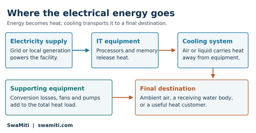
Figure 1. A simplified energy path. Supporting equipment adds to the heat load; arrows do not represent fixed energy shares. SwaMiti illustration.
The central engineering question is not just how to cool a processor. It is how to move the whole facility’s heat reliably, with acceptable electricity use, water demand and environmental impact.
1 Moving heat with air
For much of the modern data-centre era, air has been the most familiar heat-transport medium. Servers draw cooler air through their chassis. Fans move it over heat sinks and other components, and the warmed air is collected and cooled before returning to the equipment.
Computer Room Air Conditioning (CRAC) and Computer Room Air Handler (CRAH) systems are common arrangements. Separating hot exhaust from cool supply air helps prevent recirculation and unnecessary cooling effort. Raised floors are one way to distribute air, but they are not essential to every design. [3]
A useful starting point for sensible heating of a single-phase cooling medium is:

Here Q̇ is heat-transfer rate in kW, ṁ is mass flow in kg/s, cₚ is specific heat capacity in kJ/(kg·K), and ΔT is the coolant temperature rise in K. Boiling, evaporation and condensation require latent heat or a more general enthalpy balance.
For an illustrative 100 kW heat load and a 10 K temperature rise, air with cₚ ≈ 1.0 kJ/(kg·K) requires about 10 kg/s. Water with cₚ ≈ 4.18 requires about 2.4 kg/s. At assumed densities of 1.2 and 1,000 kg/m³, the corresponding volume flows are about 8.3 m³/s and 0.0024 m³/s. These are heat-balance examples, not equipment-sizing values; pressure losses and heat-transfer surfaces still govern the real design.
This difference in heat capacity per unit volume helps explain the attraction of liquid cooling. It does not establish a universal rack-power limit for air cooling or directly predict fan and pump energy.
2 Cooling towers and water consumption
Removing heat from room air is only one stage. A chilled-water system may ultimately reject that heat through an evaporative cooling tower. Some water evaporates, leaving dissolved minerals behind. Blowdown removes part of the concentrated water, and make-up water replaces losses. [3, 4]
Evaporation is water consumption; blowdown is a discharge requiring appropriate management. Its chemistry and treatment determine its impacts. Calling all blowdown “toxic sludge” would be inaccurate. Drift, leaks and operating practices also affect water demand. [4]
Water use is therefore not a fixed property of a data centre or an AI query. It depends on the cooling architecture, climate, workload and electricity supply. A facility’s direct water use should be distinguished from water associated with generating its electricity.
3 Bringing liquid close to the processor
Direct-to-chip cooling places a cold plate against a processor or accelerator. Coolant flows through internal channels, absorbs heat and carries it away. Heat still crosses the chip package, thermal interface and cold-plate wall; the liquid does not normally touch the electronic circuitry. [5]
A Coolant Distribution Unit (CDU) commonly manages circulation and transfers heat between the equipment loop and the facility loop. Its design can control temperature, pressure and flow while separating fluids with different cleanliness requirements. Not every system uses the same loop arrangement. [6]
NVIDIA’s GB200 NVL72 connects 36 Grace CPUs and 72 Blackwell GPUs in a liquid-cooled rack-scale design. Its GB300 NVL72 also combines 36 Grace CPUs with 72 Blackwell Ultra GPUs in a liquid-cooled architecture. These are concrete examples of cooling evolving with compute density, rather than evidence that every data centre requires the same solution. [1, 2]
Water-based cooling demands attention to leak detection, connectors, coolant chemistry, corrosion, material compatibility and maintenance. Equipment temperature and dew-point limits also matter. A good thermal design must remain serviceable and tolerate credible failures, not merely remove heat during normal operation. [6]
4 Immersing equipment in a dielectric fluid
Immersion cooling surrounds compatible electronics with a fluid selected for electrical insulation and thermal performance. In single-phase immersion, the fluid remains liquid. In two-phase immersion, it boils at the heated surfaces and vapour condenses elsewhere, returning liquid to the system. [7]
The fluid and hardware must be qualified together. Electrical properties alone do not establish compatibility with seals, plastics and electronic assemblies. Service procedures, fluid ageing, flammability and environmental characteristics also need assessment.
The comparison is consequently broader than “water versus oil.” Air cooling, cold plates and immersion create different thermal paths and maintenance requirements. Any of them still needs a way to reject heat outside the facility or deliver it to another user.
Liquid cooling and low water consumption are separate claims. A closed liquid loop may reject heat through dry equipment, or through a system that consumes water by evaporation. The full architecture determines the outcome.
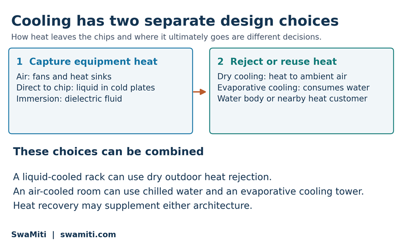
Figure 2. Two levels of cooling design, not a replacement timeline. Established approaches can coexist in a hybrid facility.
5 When waste heat becomes useful
Heat has both a quantity and a temperature. A large amount of warm water is not equivalent to high-temperature steam. To transfer heat directly, the source must be hotter than the receiving process by enough to drive heat exchange. A heat pump can raise the delivery temperature, but requires additional energy.
A practical heat-reuse project needs a nearby customer, suitable temperatures and a demand profile that matches the supply. Pipework, heat exchangers, heat pumps and backup arrangements all affect economics. The data centre still needs cooling when the heat customer cannot accept heat.
Hamina in Finland provides a real example. Google identifies seawater cooling and an offsite heat-recovery facility at its data centre. Haminan Energia’s owner, CapMan, reported first heat delivery in the fourth quarter of 2025 and inauguration in May 2026. This is operating heat-recovery infrastructure, not merely a proposal. [8, 9]
The broader lesson is location-specific: useful heat recovery depends on the surrounding energy system. A district-heating connection that makes sense in Finland is not automatically the best use of heat at a warm coastal site in India.
6 Seawater as a heat sink
Seawater cooling and underwater computing are different ideas. A land-based facility can exchange heat with seawater without placing servers underwater. Google’s Hamina facility illustrates the land-based approach. [8]
For a coastal design, the engineering assessment must consider seasonal intake temperatures, pumping distance and head, corrosion, fouling, intake protection and the effects of the discharge on the receiving environment. The sea is a potential heat sink, not an unlimited disposal route.
Heat exchangers can keep seawater separate from the controlled equipment coolant. The thermal design must include the temperature difference required across each exchanger, rather than assume that the seawater temperature is directly available at the chip.
7 Could waste heat help desalination
The idea is attractive: a data centre needs to remove heat, while a nearby coastal community needs freshwater. Whether coupling the two helps depends first on the desalination process.
Reverse osmosis (RO) uses pressure to move water through a membrane while retaining most dissolved salts. It remains a pressure-driven process; a supply of warm water does not remove the need for high-pressure pumping. [10]
DuPont’s guidance explains that increasing feed temperature, with other parameters held constant, increases both permeate flux and salt passage. Warmer feed may permit lower pressure for a specified production target, but product-water quality and membrane operating limits must still be met. A fixed percentage energy saving cannot be inferred from temperature alone. [11]
The appropriate assessment compares complete plants at the same freshwater output and quality. It includes seawater intake, pretreatment, heat exchange, pumping, energy recovery, any extra treatment and final discharge. Added equipment may consume more energy or cost more than the coupling saves.
Thermally driven desalination is another route. Kanbur and colleagues studied coupling two-phase immersion cooling to direct-contact membrane distillation at a cooling load of 0.7–1.5 kW. This is useful research evidence, but it is not proof of commercial performance at a hyperscale data centre, and it is not conventional RO. [12]
Freshwater production also leaves a concentrated residual stream. Heat recovery alone does not establish zero brine discharge or economical mineral extraction. Those would require separate processes and evidence.
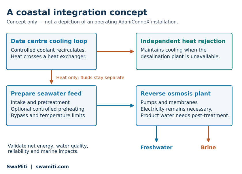
Figure 3. SwaMiti concept for evaluating optional RO feed preheating. Functional relationships only; not a process design, performance prediction or existing company installation.
8 How to test the coastal concept
The proposed coupling should be assessed against independent cooling and desalination systems delivering the same services. The heat exchanger must maintain fluid separation, while a bypass limits the RO feed temperature. An independent cooling path protects computing availability when desalination stops.
A feasibility study should establish hourly heat availability, seawater conditions, freshwater demand and membrane performance before estimating benefits. It must then account for pumping, standby capacity, capital and maintenance costs, product-water quality and marine impacts.
The figure is an engineering concept for discussion. A specific seawater temperature rise, RO energy reduction, freshwater cost saving or carbon benefit need to be developed. Those outcomes require a defined site, operating model and validated measurements.
9 The Indian context and AdaniConneX
India’s data-centre expansion makes the relationship between computing, electricity and water especially relevant. AdaniConneX’s own June 2026 account discusses scaling infrastructure alongside energy efficiency and water stewardship. It reports non-evaporative cooling approaches, rainwater harvesting and wastewater reuse. [13]
Its sustainability page also lists air-cooled chillers, reclaimed-water use and renewable-energy initiatives. These statements support a discussion of the company’s stated approach. They do not establish that it operates a data-centre waste-heat loop that preheats seawater for desalination. [14]
For India, co-location of power, computing and water infrastructure is a reasonable subject for feasibility studies. A coastal site would still need to prove technical, economic and environmental suitability.
10 What Project Natick demonstrated
Microsoft’s Project Natick explored a different route: sealed underwater data-centre modules. The Northern Isles prototype was deployed off Scotland’s Orkney Islands in 2018 and recovered in 2020 after two years. Microsoft reported a lower server failure rate than in its land-based comparison. [15]
The experiment demonstrated that subsea operation could work under the tested conditions. It did not establish underwater placement as the universal future of data centres. Deployment, retrieval, maintenance access, marine infrastructure and environmental effects remain part of the engineering comparison.
Natick should be understood as a documented research demonstration. Its reliability findings cannot be transferred automatically to every underwater design or presented as evidence that an equivalent commercial service is available everywhere.
11 Designing the complete thermal path
The evolution of cooling is not a simple sequence in which each new technology eliminates the previous one. Air, cold plates, immersion and different outdoor heat-rejection systems can coexist. Heat reuse adds another possibility when temperatures and demand align.
For technical readers, the most useful questions are concrete: Where is heat captured? What medium transports it? Where is it finally rejected? How much electricity and water does the complete system require? What happens during a failure?
Cooling will remain essential as computing develops. The opportunity is to design that thermal path well and, where a credible customer or process exists, make useful use of the heat along the way.
References
Numbered sources correspond to the article text. Web sources checked on 3 October 2026. Company statements are attributed to their publishers; conceptual assessments are identified in the text.
[1] NVIDIA. GB200 NVL72. Product architecture and processor counts. Open source
[2] NVIDIA. GB300 NVL72. Liquid-cooled rack-scale architecture. Open source
[3] U.S. Department of Energy FEMP. Cooling Water Efficiency Opportunities for Federal Data Centers. Air management and heat rejection. Open source
[4] U.S. Department of Energy FEMP. Best Management Practice 10 Cooling Tower Management. Evaporation, blowdown and make-up water. Open source
[5] Demetriou D and Quirk D. Liquid Cooling Cold Plates. ASHRAE Journal, September 2025. Public article excerpt. Open source
[6] ASHRAE TC 9.9. Water-Cooled Servers Common Designs, Components, and Processes. White paper. Open source
[7] ASHRAE Handbook 2023. Chapter 20 Data Centers and Telecommunication Facilities. SI edition. Open source
[8] Google Data Centers. Hamina Finland. Seawater cooling and offsite heat recovery. Open source
[9] CapMan. Haminan Energia advances local energy transition through a new heat recovery facility. 18 May 2026. Open source
[10] DuPont Water Solutions. Reverse Osmosis RO. Membrane separation principles. Open source
[11] DuPont Water Solutions. FilmTec Principle of Reverse Osmosis. Technical manual excerpt 45-D01538-en. Temperature effects on flux and salt passage. Open source
[12] Kanbur BB and colleagues. Multi-criteria thermoeconomic and thermodynamic assessments of the desalination-integrated two-phase liquid-immersion data center cooling system. International Journal of Energy Research, 2020. DOI 10.1002/er.5677. Public abstract. Open source
[13] AdaniConneX. Scaling India’s data centers responsibly for the AI Era Bridging People Planet and Growth. 1 June 2026. Open source
[14] AdaniConneX. Sustainability. Company statements on energy efficiency and water management. Open source
[15] Microsoft. Microsoft finds underwater datacenters are reliable practical and use energy sustainably. 14 September 2020. Project Natick results. Open source